


Introduction
In the race against time to get hardware ideas into the market, the prototyping method becomes the main cause of indecision. Should the team choose the speed of 3D printing or the waiting game of CNC machining for the best results? The wrong decision results in costly outcomes, such as the breaking of fragile prototypes during the testing phase or the creation of inflexible processes through the use of over-engineered prototypes, which can cause the costs of iteration to skyrocket. Up to 70% of the total time wasted during the project is estimated to come from wrong decisions made during the prototyping phase.
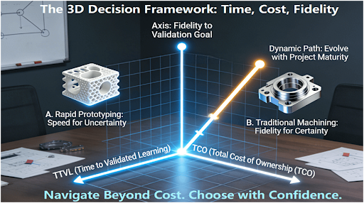
The main issue is the one-dimensional decision based on the cost or speed of the prototyping method. However, the real decision is based on the three-dimensional time value, total cost of ownership, and the fidelity match of the chosen prototyping method with the ultimate goal. The exclusion of any one of these critical elements results in the multiplication of the costs. This article presents the time cost fidelity three-dimensional decision framework. It is designed to help you determine the true value of the prototyping methods based on the current validation goal of the project.
Why Does Choosing Based on a Single Factor (Like “Speed”) Almost Always Backfire?
This section presents examples of the common decision pitfalls with real-world instances, demonstrating that the optimization for a single factor, such as “speed” or “cost,” can actually cause more project “delay” and “cost” due to the failure in the later stages of the validation process.
1. “Fast First Part” Fallacy
Take, for example, the development of a drone frame. Team A has chosen FDM 3D printing for the development of the frame, focusing on the “speed” factor. They succeeded in having the part ready for testing in just 48 hours. However, upon conducting the part’s vibration tests, the part failed due to the inherent properties of the FDM material, which has very low strength compared to the final carbon fiber composite. The team wasted another two weeks redesigning, reprinting, and re-testing the part, with the results obtained from the first test rendered useless.
2. The Premature “High-Fidelity” Trap
Team B, who designed the consumer electronics housing, has chosen the “traditional” route of CNC machining from the final production-grade aluminum. The parts turn out perfectly. However, after user testing, the product needs significant changes. This “over-investment” in fidelity too early, before the design has been “locked,” has been a waste. As the American Society of Mechanical Engineers (ASME) standards clearly indicate, the purpose of the early stages of prototyping is risk minimization, which the high-fidelity approach does not always accomplish.
3. The Necessity of a Three-Dimensional View
These examples demonstrate that a one-factor view, whether it be speed, cost, or information, is myopic. The best approach will be one that optimizes the speed, cost, and information value of the prototype. “Slow” to first part, but with conclusive results, might be better than “fast” with many iterations that provide no conclusive results. In order to understand the complete showdown between the two approaches, the cost and time guide on rapid prototyping vs traditional prototyping has some valuable information.
The Time Dimension: Is “Faster to First Part” Really the Same as “Faster to Validated Learning”?
This section “deconstructs” the “time” dimension, suggesting that the real measure is the time it takes to achieve reliable validation, rather than the time it takes to receive the first physical part, and compares the time structures for both processes.
1. Deconstructing the Timeline: Front End vs. Iteration Time
For the rapid prototyping process, such as industrial SLS/SLA, the front-end time is very short. Upload the file, and the machine starts. Receive the first part, and it will be quick. With traditional prototyping, such as CNC machining, the front-end time can be quite a bit longer. There can be CAM programming, fixture design, and setup. However, the probability that the CNC part, made from the right material with good mechanical properties, will pass the first functional test is much higher. In the “fast” process, it might take 3 iterations (3 * 2 days = 6 days), while the “slow” process might succeed after only one (1 * 10 days = 10 days).
2. The Key Metric: Time to Reliable Conclusion
Therefore, the main measure of success is Time to Validated Learning (TTVL).TTVL refers to the entire duration from design freeze until the receipt of a test result that can be used with confidence to make the next go/no, go decision.It is very valuable to have a process that shortens iteration cycle time especially during the early, uncertain stages of a project. It is also a good process to have one that produces a very high first, pass yield in the later stages where design changes are very expensive.Industrial research and development efficiency can be improved significantly by one simple but clever strategy: identifying the phase of the project and then choosing the method that best optimizes TTVL.
3. The Hidden Time Cost of Failed Tests
A prototype that does not adequately answer the validation question wastes all the time put into it, including the time to do a re-spin. If a 3D-printed component cannot survive the test loads, all the time put into designing, printing, and testing it has been a waste. The time savings of 3D printing are lost. Assessing the probability of a conclusive test is a critical component of the time analysis.
The Cost Dimension: How to Perform a Real “Total Cost of Ownership” Analysis for Prototyping?
This section outlines the framework for performing the true “Total Cost of Ownership” analysis for prototyping, not just the price of the part.
1. Expanding the Cost Model Beyond Unit Price
In order to make an effective cost comparison in prototyping, the following costs need to be considered:
l Non-Recurring Engineering (NRE) Cost: CAM programming, fixture design for CNC.
l Cost Per Iteration: The fully loaded cost of making one design revision.
l Cost of Delay: The monetary penalty of the longer design process.
l Tooling/Special Material Costs: This is applicable for traditional methods.
Rapid prototyping can have low NRE costs and moderate piece costs. Traditional CNC prototyping can have high NRE costs, but the cost per iteration can be low if the design doesn’t require re-programming.
2. The Critical Role of ‘Design Freeze’ Confidence
Clearly, the cost of change is the key factor. In the initial stages of the ‘fuzzy front end,’ when the design is still quite uncertain, a technology that has a low cost of change, such as 3D printing, is a sensible business choice even if it has a relatively higher piece cost. You’re paying for flexibility here. As the design becomes more certain and the risk of major changes diminishes, a technology that has a relatively higher NRE cost but a higher fidelity, such as CNC machining, becomes the riskier choice.
3. Quantifying the Intangible: The Cost of Wrong Data
The most expensive prototype is the one that gives you wrong data that leads to a wrong business decision. The TCO analysis must take into consideration the risk of wrong data or invalidated learning. Spending more on a high-fidelity prototype that gives you correct data is the most cost-effective way of prototyping, avoiding costly mistakes of changes or recalls down the line. Hence, a precise TCO analysis requires flexibility that is sometimes only achieved by working with a full-service provider that can offer you rapid machining services as well as traditional machining services.
H2: The Fidelity Dimension: How to Match the “Right” Prototype to Your “Verification Goal”?
This section introduces a “Goal-Process” matching matrix that helps readers match the prototype’s physical properties with the question they are trying to answer.
1. Categorizing Verification Goals
Not all prototypes are created equal. Define your primary goal:
l Form, Fit, and Assembly (FFA): Testing size, shape, and how parts mate together. High geometric accuracy is a requirement. CNC machining or high-resolution SLA is usually the way to go.
l Functional Performance: Testing real-world conditions like load, temperature, or stress. Material properties and structural integrity are a must. CNC machining from production-grade metals or composites is usually required.
l User Experience & Aesthetics: Testing look, feel, and overall user experience. Surface finishes and “perceived quality” are critical. Technologies like Multi-Jet Fusion (MJF) with high finishes or vacuum casting from a master pattern work very well here.
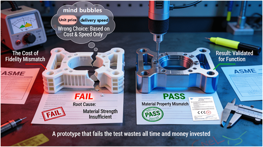
2. The Cost of Fidelity Mismatch
If the fidelity of the prototype is low while the question being asked is high-fidelity, it is a waste of time. A plastic 3D-printed part is not the same as a metal one in fatigue life. A CNC “looks like” model is not the same as one designed to gather useful data on the usability of the product. The only way forward is to make sure the fidelity of the prototype matches the capability being asked. This is an important part of being an engineer, as the Society of Manufacturing Engineers (SME) points out in their publications.
3. The Path to Production-Ready
Fidelity can also mean the path to production. A process for making the part that is the same as the production process (such as CNC machining the final material) is the best way to get data. A process that is different (such as 3D printing) can get you some data, but the material and process are still risks. The path you choose can get you toproduction-ready status sooner.
Blending all Components: A Real, World Guide to Your Prototyping Decision
This part will combine the three, dimensional model into a standalone decision flowchart. A very simple case example is going to be used for illustrating the application.
1. The Decision Flowchart: A Step, by, Step Guide
The core question should be defined: What is the one piece of information this prototype has to give? (for instance, “Is it the right size?” “Will it withstand 10, 000 cycles?”)
l Evaluate the Design Stability: How likely is it that the total design will be substantially different after the prototype test? (High, Medium, Low) This decides your level of willingness to pay for change cost.
l Score the Options: Each viable process (SLS, CNC, Vacuum Casting, etc.) has a score based on:
l Time: TTVL estimate.
l Cost: TCO estimate for 1-3 iterations.
l Fidelity: Match with the core question (1-5 scale).
l Select & Execute: Choose the one with the best weighted score based on your current project priorities.
2. Case Study: Medical Device Enclosure
1. Stage 1 (Concept): Goal = Ergonomics and User Interface. Choice = 3D Printing (SLA). High speed, low C.O.C., and adequate fidelity for feel.
2. Stage 2 (Alpha): Goal = Waterproof Seal and Assembly Fit. Choice = CNC Machined Aluminum. High fidelity for critical seals and acceptable C.O.C. as design stabilizes.
3. Stage 3 (Beta): Goal = Biocompatibility and Sterilization Cycles. Choice = CNC Machined Final Plastic via ISO 13485 supplier. Maximum fidelity and compliance for final validation.
3. The Iterative Nature of the Framework
This framework is not used once but repeatedly. The best choice is the one that changes as the project progresses through the process of moving from uncertainty to certainty.
How to Evaluate a Supplier’s Ability to Guide You Through This Decision, Not Just Execute an Order?
The final section is a checklist to help you assess the strategic guidance ability of a would-be manufacturing partner.
1. The “Consultative First Question” Test
Does a supplier you are trying to get in touch with for the first time immediately inquire about how you are going to verify the part, what environment the part will operate in, and what the stage of development the part is currently in before they gather any information from you? Or they ask for a file to quote straight away?Basically, a good supplier who is interested in your success will try to understand your problem first before they offer a solution.
2. Transparency and Comparative Analysis Capability
Ask them to perform a parallel comparative analysis for your part specifically. Can they break down a would-be solution for you on a side-by-side basis, showing lead times, costs, materials, and pros/cons of, say, SLS printing versus CNC machining? A would-be supplier’s ability to perform this type of analysis is a strong indication of their process knowledge and desire to assist you in making an informed decision — a key attribute of true precision manufacturing expertise.
3. Operational Flexibility and System Integration
Does the business and shop floor system enable smooth transitions between rapid prototyping services and traditional prototyping methodologies? Can a design, after being validated using 3D printed plastics, be quickly moved to CNC machining for the next version without requiring the original specifications to be re-justified? A partner with this capability can help your optimal path forward, changing as needed to ensure your velocity.
Conclusion
In hardware innovation, the selection of a prototyping methodology is a complex optimization problem rather than a simple binary choice. Using the three-dimensional decision process, we can now precisely direct limited R&D investment to the areas where the greatest learning value is achieved. We can thus systematically minimize the time required to develop a product, control the cost of iteration, and ensure that each prototype takes us another step towards success.
FAQs
Q: What is essentially the difference in the result between fast and traditional prototyping?
A: Rapid prototyping concentrates on the fastness and freedom of geometry for form/fit checks and initial concepts, frequently sacrificing materials. Traditional prototyping is centered on material authenticity and performance for functional testing, frequently sacrificing the speed. What you learn about your design depends on what method you choose.
Q: What can I do to make sure a fair apples, to, apples comparison is made for my specific project needs?
A: You may ask the service providers to use the same 3D CAD file and verification objectives for a comparative breakdown of lead times, cost per iteration, tolerances, and materials.
Q: For a quantity of 50 to 100 units, what approach is generally more cost-effective for a pilot run of parts?
A: Ah, now we are in the critical crossover area! For simpler designs, the winner may be rapid tooling, such as aluminum molds. For more complex designs, CNC machining from billet may be the winner.
Q: What are your procedures for accommodating changes in the design during the prototyping phase for each method?
A: With the rapid prototyping method (3D printing), the process changeover cost is essentially zero, just a matter of changing the file. With the traditional method (CNC), it can be more expensive, requiring re-programming and new setups. Cost of change is an important consideration at the early stages.
Q: What are your procedures for protecting intellectual property with regard to the designs shared for the purpose of prototyping?
A: With regard to protecting intellectual property, reputable manufacturers will be operating under very strict Non-Disclosure Agreements (NDAs). Make sure your NDA has been executed before anything else. In addition, it would be worthwhile asking them about their data security systems.
Author Bio
This article is based on substantial hands-on experience in the areas of agile product development and precision manufacturing. As a manufacturing partner certified to ISO 9001, IATF 16949, and AS9100D, full-spectrum services are provided by LS Manufacturing from rapid prototyping through production, all aimed at assisting clients in developing the most optimal validation strategy through front-end engineering collaboration. Send your design requirements and validation objectives to them today to receive a complimentary report on their “Prototyping Process Path Planning and Preliminary TCO Analysis.”